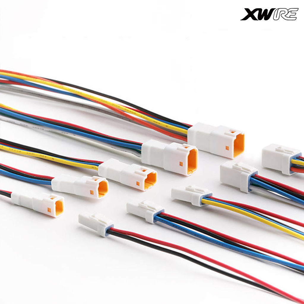
A reliable Wiring Harness serves as the central nervous system of any modern Electric Two Wheeler. Real-world component failures rarely stem from core motor or battery defects. Instead, they usually trace back to faulty connectors or degraded signal shielding. As manufacturers rapidly scale up assembly lines, picking the right wiring setup becomes critical. It shifts quickly from a simple electrical continuity check to a highly complex engineering decision.
You must carefully balance thermal management, complete waterproofing, and modular design requirements. Getting these elements wrong often leads to severe safety hazards and expensive warranty recalls. This guide provides a comprehensive technical evaluation framework. It will help you confidently shortlist and select cables and connectors for your builds. You will learn how to ensure vehicle reliability, meet strict safety compliance standards, and maintain highly scalable assembly operations. We will cover wire sizing, environmental protection limits, and modern supplier validation protocols in depth.
Key Takeaways
Modularity is essential: Separating high-current power lines from sensitive data/signal cables prevents electromagnetic interference (EMI) and simplifies maintenance.
Environmental protection dictates lifespan: IP67+ rated connectors and appropriate wire gauges (AWG) are non-negotiable for real-world reliability.
System alignment reduces risk: The harness must be explicitly rated to bridge your specific Low-Voltage Power Battery Pack Solution with the controller and motor.
Supplier validation requires hard data: Shortlist suppliers who utilize specialized new energy testing equipment rather than manual pin-checks.
The Architecture Shift: Why an Electric Two Wheeler Requires Specialized Wiring
Understanding the Business Problem
Many new system integrators mistakenly adapt traditional ICE (Internal Combustion Engine) motorcycle harnesses for electric vehicles. This strategy fails rapidly. Traditional ICE harnesses focus entirely on 12V lighting and basic ignition circuits. They manage very low continuous currents. In stark contrast, EV harnesses face massive electrical demands. They must carry sustained high currents to drive the motor effectively. They also handle extreme thermal loads during rapid acceleration. Furthermore, they route highly sensitive digital communications. Modern EV controllers rely heavily on CAN bus signals to operate safely.
The Cost of Getting It Wrong
Undersized wiring fundamentally restricts power delivery. This creates substantial voltage drops across your system. You will immediately notice reduced vehicle range. Top-speed performance suffers drastically as a result. Even worse, localized overheating happens quickly. Sustained high loads cause catastrophic melting at the battery or controller connectors. This poses a severe fire risk to the rider.
Establishing an Evaluation Baseline
You must establish a strict evaluation baseline for all prospective designs. Assess all proposed harness architectures against three critical pillars:
Voltage Drop Tolerances: Measure resistance across the longest cable runs to ensure minimal power loss.
Thermal Dissipation Capabilities: Verify the cables shed heat effectively under peak load scenarios.
EMI Shielding Effectiveness: Ensure power lines do not induce noise into nearby data lines.
Common Mistake: Do not rely solely on theoretical wire ratings. Always test the harness under actual load conditions inside a physical vehicle frame. Ambient temperature significantly alters thermal dissipation rates.
Core Technical Evaluation Criteria for Wiring Harnesses
Current Capacity and Wire Gauge (AWG)
Mapping peak versus continuous current draws is your first technical task. Vehicles draw massive peak amps when accelerating from a dead stop. They draw much lower continuous amps while cruising. Ensure your phase wires and battery cables handle both extremes safely. We recommend referencing industry-standard AWG (American Wire Gauge) classifications. You often need 8-10 AWG cables for high-power motor phases. However, avoid unnecessarily thick cables. Over-sizing wires adds costly weight to the vehicle. It also reduces cable flexibility during assembly.
Standard EV Wire Sizing Reference Matrix
Application Area
Recommended AWG
Typical Current Range (Continuous)
Primary Concern
Battery Power / Main Trunk
6 AWG - 8 AWG
50A - 100A+
Thermal melting, severe voltage drop
Motor Phase Wires
8 AWG - 10 AWG
40A - 80A
Flexibility, high-temperature resistance
Lighting and Accessories
16 AWG - 18 AWG
5A - 15A
Physical routing, mechanical abrasion
CAN Bus / Sensor Signals
20 AWG - 24 AWG
< 2A
EMI shielding, pin corrosion
Connector Standards and Environmental Sealing
Evaluate connectors for rigorous environmental protection. You must demand IP67 or IP68 ratings for external components. These standards guarantee prevention of water ingress. They eliminate the risk of internal pin corrosion. Look for positive-locking mechanisms on all vital connections. They prevent accidental disconnects during rough rides. Additionally, ensure the connector housings offer dielectric grease compatibility. This grease provides a secondary moisture barrier in high-vibration environments.
Routing and Flexibility Constraints
Assess the minimum bend radius of all high-voltage cables carefully. Tight bends severely strain internal copper strands. Over time, these fine strands fracture. This structural damage increases electrical resistance and generates dangerous heat. Evaluate the durability of the outer sheathing materials. Specialized PVC or PTFE (Teflon) jackets perform exceptionally well. They must withstand prolonged UV exposure, sub-zero temperatures, and constant mechanical abrasion against the metal chassis.
Integrating the Low-Voltage Power Battery Pack Solution
Ensuring Seamless Compatibility
The wiring layout must seamlessly interface with the onboard Battery Management System (BMS). It connects directly to the Low-Voltage Power Battery Pack Solution. A mismatched connector causes immediate system communication faults. These faults easily trigger false diagnostic codes. They can also force the controller into a restricted "limp mode". Always verify pinout alignments between the battery output and the main trunk line.
Managing Thermal Considerations
Connectors located at the main battery terminal endure the highest thermal stress. They handle the entire electrical load of the vehicle continuously. Evaluate the supplier’s specific choice of terminal materials. Gold-plated pins offer significantly lower electrical resistance than standard tin-plated pins. They mitigate heat generation effectively. This material choice dramatically extends the operational lifespan of the connection.
Implementing Safety Disconnects
Look for integrated anti-spark connectors in the design. High-voltage connections naturally create small electrical arcs during initial mating. Anti-spark technology utilizes pre-charge resistors to prevent this damaging arc. Ensure accessible emergency disconnect routing as well. Technicians and emergency responders need a fast, intuitive way to sever power. This accessible design ensures compliance with international safety standards.
Best Practice: Always position the main safety disconnect switch in an easily reachable area under the seat or near the central chassis frame. Label it clearly with high-contrast safety colors.
Adapting to High- and Low-Speed Vehicle Components Solutions
Embracing Modular Architecture
Standardizing a single harness design across a diverse fleet requires a smart modular approach. It must adapt easily to a comprehensive High- and Low-Speed Vehicle Components Solution. Modularity sharply reduces inventory complexity for manufacturers. It also accelerates assembly line training. Instead of building unique harnesses for every vehicle tier, engineers design a universal central trunk. They then attach specialized sub-harnesses for distinct vehicle models.
Enforcing Signal vs. Power Separation
Ensure the physical layout isolates high-power motor phases completely. Keep them far away from low-voltage throttle, display, and sensor signals. High-current power cables naturally emit strong magnetic fields. These fields induce unwanted electrical noise into nearby data lines. This EMI jitter causes jerky throttle responses and erratic speedometer readings. Use heavy braided shielding on critical data lines to block this interference.
Maximizing Plug-and-Play Capability
Evaluate the component swapping process meticulously. You might want to upgrade a model from a low-speed commuter motor to a high-speed performance motor mid-production. The harness architecture should allow this seamlessly. You should never have to rewire the main trunk. Standardized multi-pin connectors enable true plug-and-play manufacturing. This flexibility lowers labor times and reduces tooling changeovers on the factory floor.
Evaluating Supplier Quality and Testing Protocols
Demanding Advanced Verification Equipment
A reliable B2B supplier must definitively prove their quality control capabilities. Manual pin-checking is entirely insufficient for modern EV production. They need comprehensive automated testing. Look for documented use of a New Energy Production and Testing Equipment Solution. This advanced equipment verifies continuity, precise resistance, and high-voltage insulation accurately. Specifically, require mandatory Hipot (High Potential) testing. Hipot testing applies extremely high voltage to ensure insulation integrity holds under stress without leaking current.
Verifying Compliance and Certifications
Request hard proof of international certifications immediately. You need RoHS, UL, or CE compliance for all internal wire materials and external connectors. These documents guarantee base material safety and environmental compliance. They prove the plastics used will not degrade prematurely. They also confirm the materials resist chemical exposure from road salts and cleaning solvents.
Ensuring Component Traceability
Ensure the manufacturer provides strict batch tracking. They must supply detailed topological diagrams for every single revision. You absolutely need these documents for effective field troubleshooting. When a customer reports a rare electrical fault, traceability allows your engineers to isolate the exact production batch. This limits the scope and cost of potential safety recalls.
Shortlisting Logic and Implementation Risks
Weighing Off-the-Shelf vs. Custom OEM
Compare the development costs carefully. Custom harnesses require longer lead times and higher upfront engineering fees. They require dedicated tooling molds. However, off-the-shelf solutions often demand awkward routing compromises. They might leave dangerous excess cable slack near moving suspension parts. Custom OEM designs ultimately offer superior fitment, lower weight, and higher reliability for high-volume production runs.
Executing the Prototyping Phase
Always mandate a rigorous first-article inspection (FAI). Never skip the physical prototype phase. Follow these vital validation steps:
Install the sample harness directly onto a physical vehicle frame.
Turn the handlebars fully left and right repeatedly. Check for dangerous cable tension near the steering column.
Compress the front and rear suspension fully. Ensure cables do not stretch, pinch, or rub against the tires.
Spray the connected harness with a high-pressure water hose to simulate heavy rain and check for dashboard fault codes.
Defining Next Steps with a TRD
Draft a comprehensive Technical Requirements Document (TRD). Detail your exact peak amps, required connector brands, and strict length tolerances. Send this TRD to three or four shortlisted manufacturers. Request detailed technical spec sheets and engineering blueprints in return. Compare their proposed wire gauges and testing methodologies side-by-side. Choose the partner who demonstrates the deepest understanding of thermal management and automated quality control.
Conclusion
Selecting the optimal wiring setup remains a critical exercise in risk mitigation. You must prioritize correct AWG sizing, IP-rated connectors, and rigorous automated testing over chasing initial cost savings. The finest electrical architecture acts as a seamless, invisible bridge. It effortlessly connects your battery pack to all vital vehicle components without generating excess heat or dropping voltage. Take action by consulting your engineering team today. Finalize your pinout diagrams and begin sourcing suppliers who possess proven, automated testing capabilities. Doing so guarantees a safer, more reliable product for your end users.
FAQ
Q: What is the minimum IP rating required for an electric two wheeler wiring harness?
A: IP67 is the absolute standard baseline. It ensures complete protection against heavy dust and temporary water submersion. This level of defense is critical for exposed two-wheeler frames facing rain, deep puddles, and high-pressure washing cycles.
Q: How does a harness for a low-speed e-bike differ from a high-speed electric motorcycle?
A: High-speed vehicles require much thicker gauge wires (like 8 AWG) to manage higher sustained amps safely. They also need more robust EMI shielding to protect complex CAN bus communication systems. Finally, they demand stricter thermal management at all major connection points.
Q: Why is my EV wiring harness experiencing voltage drop?
A: Voltage drops are usually caused by inadequate wire gauges for the length of the run. Poor quality connector crimps also increase resistance significantly. Additionally, degraded, loose, or corroded battery terminal connections obstruct efficient power delivery.
Q: Should data and power lines be bundled together?
A: No. Best practice dictates physical separation or heavy shielding. This prevents the high-current power lines from inducing electrical noise. That noise easily disrupts sensitive throttle inputs or critical motor sensor signals, causing erratic vehicle behavior.